- Welcome to InterCAD Systems Pvt. Ltd.
- Welcome to InterCAD Systems Pvt. Ltd.
+91 98470 32588
sales@intercadsys.com
+91 906 136 5000
support@intercadsys.com
+91 906 111 1060
training@intercadsys.com
+91 98470 32588
sales@intercadsys.com
+91 906 136 5000
support@intercadsys.com
+91 906 111 1060
training@intercadsys.com

Modeling, analysis and design of bridge structures have been integrated into CSiBridge to create the ultimate in computerized engineering tools. The ease with which all of these tasks can be accomplished makes CSiBridge the most versatile and productive software program available on the market today.
CSiBridge automatically creates joints at structural object intersections or internal joints when meshing structural objects. Joint coordinates and information may be displayed on screen in the model window
or in tabular format.
In CSiBridge, Tendons are easily drawn as independent objects, with geometry specified as straight lines, parabolas, circular curves, or other arbitrary shapes. They can also be defined parametrically to drape inside of a box girder. Tendon loads, including all losses, are easily defined.
Moving load analysis is available in CSiBridge to compute influence lines and surfaces for traffic lanes on bridge structures and to analyze these structures for the response due to vehicle live loads. Vehicles can also be moved in a multi-step analysis. This can use either multi-step static load cases or time-history load cases, the latter of which can be linear or nonlinear.
Fully integrated concrete frame design in CSiBridge includes: required area of steel calculations, auto selection lists for new member sizing, implementation of design codes, interactive design and review, and comprehensive overwrite capabilities.
Bridge Object Model
The bridge object model is a comprehensive assemblage of components that make up the entire bridge
model. The parametric model is managed through the bridge object model. This includes: the modeling
of deck sections, diaphragms, bearings, restrainers, foundation springs, superstructure variation,
abutments, bents, hinges, tendon layouts, and more.
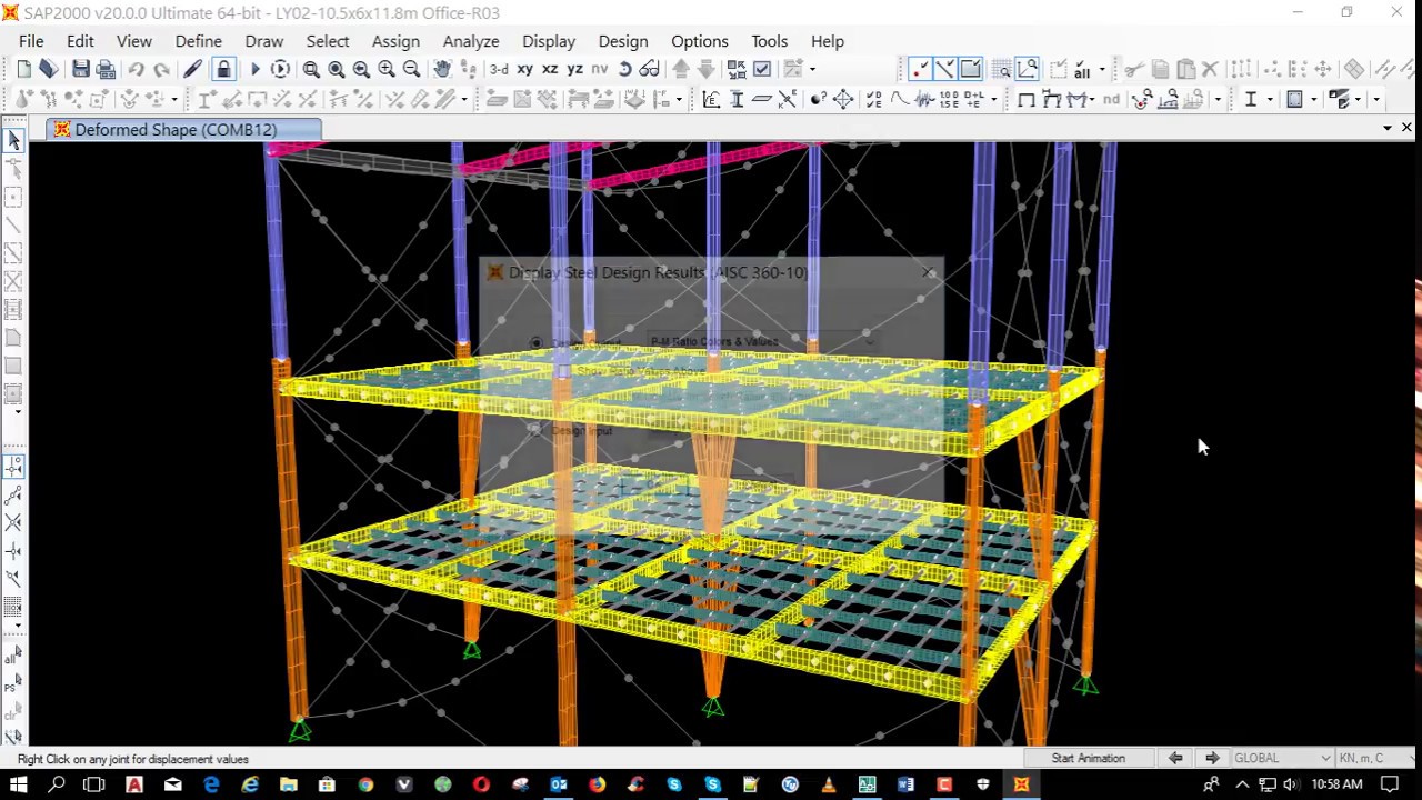
The SAP name has been synonymous with state-of-the-art analytical methods since its introduction over
30 years ago. SAP2000 follows in the same tradition featuring a very sophisticated, intuitive and
versatile user interface powered by an unmatched analysis engine and design tools for engineers
working on transportation, industrial, public works, sports, and other facilities.
SAP2000 has a wide selection of templates for quickly starting a new model. SAP2000 includes parametric templates for the following types of structures: Simple Beams, 3D Trusses, 3D Frames, Storage Vessels, Staircases, Dam Structures, and Pipes.
SAP2000 will automatically generate and apply seismic and wind loads based on various domestic and international codes. SAP2000 also has a sophisticated moving load generator that allows users to apply moving loads to lanes on frame and shell elements.
SAP2000 can perform both linear static and multi-step static analysis. The linear static analysis of a structure involves the solution of the system of linear equations represented by K u = r. Certain types of load patterns are multi-stepped, meaning that they actually represent many separate spatial loading patterns applied in sequence. These include the vehicle, live, and wave types of load patterns.
Linear (bifurcation) buckling modes of a structure can be found under any set of loads. Buckling can be calculated from a nonlinear or staged-construction state. Full nonlinear buckling analysis is also available considering P-delta or large deflections effects. Snap-through buckling behavior can be captured using static analysis with displacement control. Dynamic analysis can be used for modeling more complex buckling, such as follower-load problems.
 SAP2000 -Brochure.pdf

SAFE is the ultimate tool for designing concrete floor and foundation systems. From framing layout all
the way through to detail drawing production, SAFE integrates every aspect of the engineering design
process in one easy and intuitive environment. SAFE provides unmatched benefits to the engineer with
its truly unique combination of power, comprehensive capabilities, and ease-of-use.
Design strips are used to define how reinforcement requirements are to be calculated. SAFE can automatically define the strips for you, or you can define them yourself.
View database tables containing all input data, analysis results, and design results in a tabular format within the SAFE user interface. Users can filter, sort, and query the table data and print or save the data to Microsoft Access, Excel, HTML, or Text formats.
Finite element based design does not require design strips. It is ideal for complex geometry where defining strips can be difficult. The design will output contour plots of rebar density by averaging of peaks over user defined widths. This helps with identifying "hot spots" for reinforcing design.
SAFE is ideal for modeling foundations, basemats, and footings. Easily model soil supports and zero tension soil models with uplift analysis. The area assignment of soil supports is based on the subgrade modulus, and they automatically adjust whenever the mesh changes. Basemat foundation models can include pedestals, walls, columns, beams, and piles in addition to the foundation area.
SAFE allows for an unlimited number of load cases and combinations. Design combinations will automatically be added based on the selected design code, including strength and service combinations. Linear additive, envelope, absolute additive, SRSS, and range functions have been built in to the load combination editor for efficiency.
SAFE -Brochure.pdf
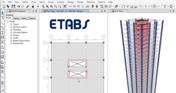
The innovative and revolutionary new ETABS is the ultimate integrated software package for the structural analysis and design of buildings. Incorporating 40 years of continuous research and development, this latest ETABS offers unmatched 3D object based modeling and visualization tools, blazingly fast linear and nonlinear analytical power, sophisticated and comprehensive design capabilities for a wide-range of materials, and insightful graphic displays, reports, and schematic drawings that allow users to quickly and easily decipher and understand analysis and design results.
ETABS offers a single user interface to perform: Modeling, Analysis, Design, and Reporting. A new model explorer is available for quick access to objects, properties, and forms.
In ETABS, grids can be defined as cartesian, cylindrical, or general free-form grid systems. There is no limit to the number of grid systems in a model, and they can be rotated in any direction or placed at any origin within the model.
Multi-tower buildings can now easily be modeled by using the new tower feature. Defining towers in an ETABS model allows users to define unique story levels and grid systems for different building structures within the same ETABS model. For example, ETABS models can share a podium level and then separate into towers on higher floors.
Live-load-reduction factors may be assigned on a member-by-member basis. This may be done either within the graphical user interface, once design is complete, by right-clicking on a member, or it may be done using interactive database editing.
P-delta analysis captures the softening effect of compression and the stiffening effect of tension. A single P-delta analysis under gravity and sustained loads can be used to modify the stiffness for linear load cases, which can later be superposed. Alternatively, each combination of loads can be analyzed for full nonlinear P-delta effects. P-delta effects are included for all elements and are seamlessly integrated into analysis and design.
ETABS has a wide selection of templates for quickly starting a new model. At this model template stage, the user has the ability to define grid and grid spacing, the number of stories, the default structural system sections, default slab and drop panel sections, and uniform loads (specifically dead and live loads).
Etabs Brochure.pdf
We commit to help you work faster and smarter. Let us show you how
Contact us